Key Takeaways
- A thermostat controls your furnace by sending signals through a series of wires.
- The W wire is the heating wire that signals the furnace to start the heating cycle.
- Always match each wire to its terminal and follow wiring diagrams when installing a furnace thermostat.
A furnace thermostat is the control center of your heating system. It constantly monitors indoor conditions and uses a set of wires to signal the furnace to maintain your set temperature.
Whether you’re installing a new thermostat or troubleshooting an issue, a clear understanding of furnace thermostat wiring makes all the difference. This guide breaks down various thermostat wires and how to identify common wiring problems to keep your system running smoothly.
Furnace Thermostat Wires & Their Functions
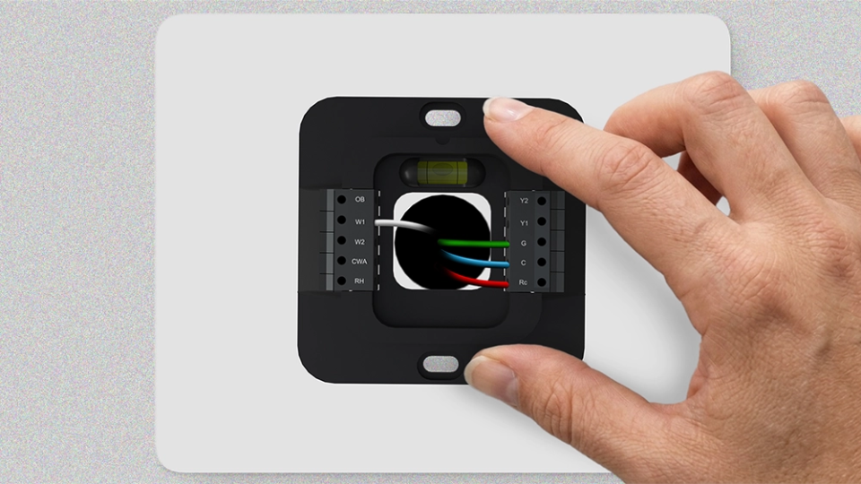
Modern furnace systems use low-voltage wiring for communication between the thermostat and the furnace control board. Each thermostat wire serves a specific purpose, and connecting it correctly is essential to reliable system performance.
R, Rc, or Rh
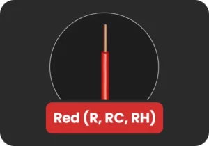
The R, Rc, or Rh wire supplies 24V power to the thermostat. It is the primary power wire and is essential for the thermostat operation.
If your system has only one R wire, whether labeled R, Rc, or Rh, it typically connects to the Rc terminal on the thermostat.
Budget-friendly smart thermostat for central HVAC systems. A thermostat that guarantees savings.
Award-winning smart thermostat for mini-splits. Technology that goes above & beyond.
Sleekest smart thermostat for mini-split, window & portable ACs. A design that magically blends.
Smart mini-split thermostat that is engineered for affordable comfort. Small in size, big in benefits.
G Wire
The G wire controls the furnace blower fan independently of the heating or cooling function. When the thermostat calls for the fan to run, either as part of a heating or cooling cycle or manually when the fan-only mode is selected, the G wire sends the signal to activate the fan. A loose or disconnected G wire will result in no airflow.
W or W1
The W or W1 wire, typically white, is the primary heating wire and one of the most important connections in any furnace wiring setup. When the thermostat detects that the indoor temperature has fallen below the set point, it sends a signal via the W wire to activate the furnace burner and begin the heating cycle.
Without a properly connected W wire, the furnace will not respond to heating calls from the thermostat. If your furnace is failing to heat, this is the first connection to inspect.
W2
The W2 wire is used in two-stage heating systems. In a two-stage furnace, the first stage operates at a lower output for moderate conditions, while the second stage delivers full capacity during periods of extreme cold. The second stage activates only when temperatures drop significantly, and the first stage alone cannot meet demand.
If your furnace is single-stage, the W2 wire will not be present.
C-Wire
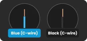
The C wire, or common wire, is necessary for smart thermostats and completes the 24V circuit between the thermostat and the furnace control board, providing a continuous and stable power supply to the thermostat.
Older thermostats with simple controls did not require a C-wire because they drew minimal power. However, modern smart thermostats with digital displays require a consistent power source to operate their screens, Wi-Fi connectivity, and advanced features.
If your existing wiring does not include a C wire, options include running a new wire, repurposing an unused wire in the existing cable, or using a C-wire adapter.
Furnace Thermostat Wiring Diagrams
Wiring configurations vary depending on the number of stages involved or if you have additional accessories configured.
Note: Always refer to both your thermostat’s installation manual and your furnace’s wiring diagram before making any connections. Wiring configurations can vary between manufacturers, and confirming compatibility beforehand prevents damage to system components and ensures reliable performance.
Here are the most common configurations:
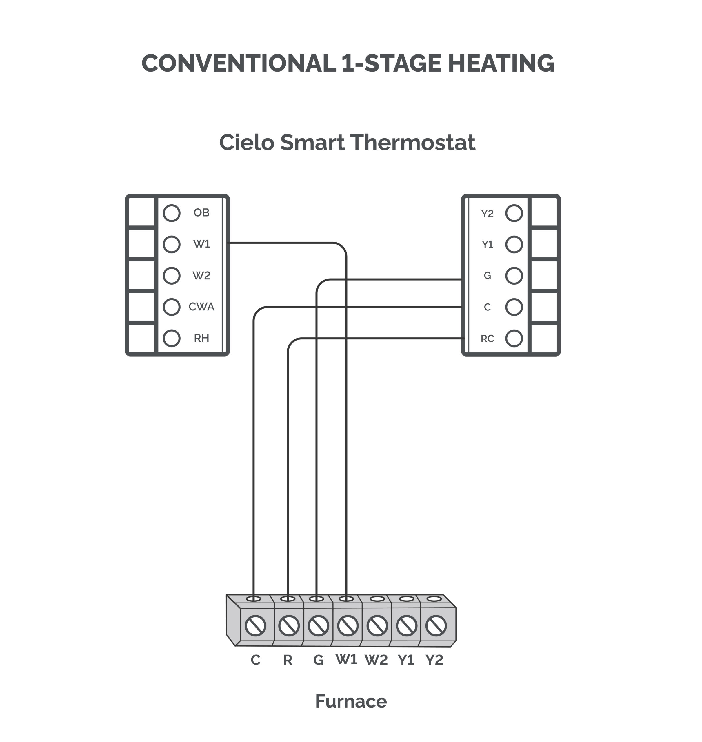
Conventional 1-Stage Heating
Required terminals: Rc, W1, C, G
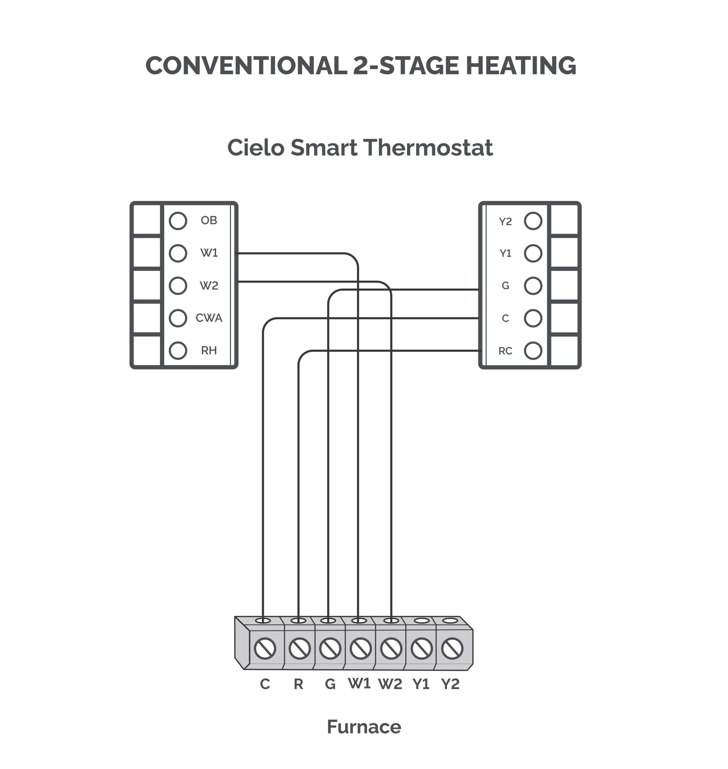
Conventional 2-Stage Heating
Required terminals: Rc, W1, W2, C, G
Troubleshooting Furnace Thermostat Wiring Issues
Below are the most common furnace wiring issues and how to address them.
Loose Wiring Connections
Loose thermostat wiring is one of the most common causes of furnace malfunctions. A wire not securely fastened at its terminal can cause intermittent heating or erratic behavior.
How to address it: Turn off the furnace power at the circuit breaker before inspecting any wiring. Carefully examine each terminal on both the thermostat and the furnace control board. Give each wire a gentle tug to confirm it is seated properly. If any wire pulls free easily, reinsert it and ensure it is clamped securely. Restore power and test the system.
Furnace Thermostat Not Powering On
If the thermostat display is blank or completely unresponsive, the issue is commonly related to the power supply. This is caused by an improperly connected R wire, which supplies power to the thermostat.
If your smart thermostat turns on but the display flickers, it may be due to a loose C-wire.
How to address it: Begin by checking the circuit breaker and resetting it if necessary. If everything looks fine, verify that the R and C wires are configured correctly.
Furnace Not Responding to Heating Calls
If your thermostat is powered and functioning, but the furnace does not respond when heating is called for, the W-wire connection is the first place to check. A disconnected, loose, or incorrectly configured W wire will prevent the furnace from receiving the heating signal.
How to address it: Make sure that the W wire is inserted into the right terminal on the thermostat.
Furnace Fan Not Operating
If the furnace heats but no air is being distributed through the vents, the G wire connection is likely at fault. A loose or missing G wire will prevent the blower fan from receiving the signal to operate.
How to address it: Inspect the G wire connection at both the thermostat and the furnace control board. Ensure it is securely connected to the G terminal at both ends.
In Conclusion
Whether you are installing a new thermostat or diagnosing an existing issue, understanding furnace thermostat wiring is crucial. Always consult your thermostat’s installation manual and the furnace thermostat wiring diagram before making any changes. Taking the time to verify each connection is a small step that can prevent significant issues down the line.