Key Takeaways
- Heat pump thermostat wiring differs from conventional HVAC systems as it utilizes an additional O/B wire.
- The O/B wire allows the system to switch between heating and cooling.
- Proper heat pump operation depends on matching each wire to the correct thermostat terminal during installation.
Heat pump thermostat wiring isn’t the same as traditional HVAC wiring, and getting it right is highly important. Incorrect wiring can cause your system to run in the wrong mode, leading to inefficient operation, discomfort, and higher energy costs.
This guide covers everything you need to know about heat pump thermostat wiring, from understanding wiring terminals to step-by-step installation and troubleshooting.
Meet the HVAC Experts
- Glenn Gault is an HVAC Expert & CEO of Gault Heating & Cooling.
- Paul Blanchard is an HVAC technician at Lightning Service Inc.
Understanding the Basics of Heat Pump Thermostat Wiring
A heat pump does not generate heat as a furnace does. Instead, it transfers heat, extracting it from the indoor air and expelling it outside in summer. This process is reversed during winter. As the same unit handles both functions, the thermostat wiring must be configured accordingly. In addition to the standard wires found in conventional systems, such as those controlling the power, fan, and common connections, a heat pump thermostat requires a dedicated reversing valve wire, typically labeled O/B. This wire signals the system to switch between heating and cooling modes and is fundamental to heat pump operation.
Budget-friendly smart thermostat for central HVAC systems. A thermostat that guarantees savings.
Award-winning smart thermostat for mini-splits. Technology that goes above & beyond.
Sleekest smart thermostat for mini-split, window & portable ACs. A design that magically blends.
Smart mini-split thermostat that is engineered for affordable comfort. Small in size, big in benefits.
Thermostat Wires: Color Codes & Their Functions
Thermostat wires are generally color-coded, but variations are common across different setups.
HVAC expert Paul Blanchard explains, “There are standard wire colors most of the time, like red for power, yellow for cooling, and green for the fan, but in the field, it doesn’t always match up that way. It’s better to look at where the wire is actually connected at the unit and match it from there. That’ll save you from a lot of wiring issues.”
R, Rc, or Rh
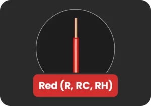
The R wire provides 24V AC power to the thermostat and is essential for system operation.
If you only have one R wire (labeled R, Rc, or Rh), it typically connects to the Rc terminal on the thermostat.
If an Rc wire is not present, the Rh terminal can serve as both the heating and cooling power source, and vice versa.
Y or Y1
The Y or Y1 wire controls the compressor, the core component that heats and cools a heat pump system. Whenever the thermostat calls for heating or cooling, it activates the compressor through this wire.
As HVAC expert Glenn Gault, CEO of Gault Heating & Cooling, explains, “On conventional HVAC systems, Y means cool, but on heat pumps, Y runs both heating and cooling, and the thermostat itself decides what mode it needs to run at the moment.”
Y2
This wire controls the second stage of the compressor and is present in multi-stage heat pump systems. It activates the second stage when additional heating or cooling capacity is needed. This is required in extreme weather conditions or when the system needs to reach the desired temperature more quickly. If your system is single-stage, this wire will not be present.
G Wire
The G wire controls the fan function of your heat pump. It ensures that air is properly circulated throughout your home during heating, cooling, or when the fan is set to run independently. Without the G wire, users cannot control the fan operation through the thermostat.
W, W1
In heat pump systems, the W or W1 wire typically controls auxiliary heat, rather than primary heating.
Auxiliary heat acts as a backup when the heat pump cannot maintain the desired indoor temperature in cold weather. This backup heat may come from electric heat strips or a secondary heating system, such as a furnace.
In some systems, this function may also be labeled as E (Emergency Heat), which is used when the heat pump malfunctions or in case of extreme weather conditions.
W2
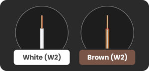
The W2/ Aux2 wire typically controls the second stage of auxiliary heat.
O, B, or O/B Wire
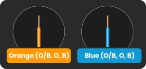
The O/B wire controls the reversing valve, the component that switches your heat pump between heating and cooling modes. Depending on the thermostat, you may find two separate O or B terminals, or a combined O/B terminal.
In some heat pumps, the O wire energizes the reversing valve in cooling mode, while in others, the B wire energizes it in heating mode. This signal activates the reversing valve to generate warm or cool air.
Incorrect wiring or configuration of this terminal will reverse system operation, causing the system to cool when heat is called for and heat when cooling is required. Always verify your system specifications before wiring.
C-Wire
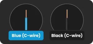
The C-wire (common wire) provides a continuous 24V power to the smart thermostat.
Unlike the R wire, which supplies power, the C-wire completes the circuit, ensuring a constant flow of power. It is essential for smart thermostats to support features like touchscreens, Wi-Fi connectivity, and advanced controls.
Equip your HVAC system with smart features and achieve the perfect balance between comfort & savings.
Learn more
Heat Pump Thermostat Wiring Diagrams
Depending on the type of heat pump you have, connect each wire to its corresponding terminal as shown in the following heat pump thermostat wiring diagrams.
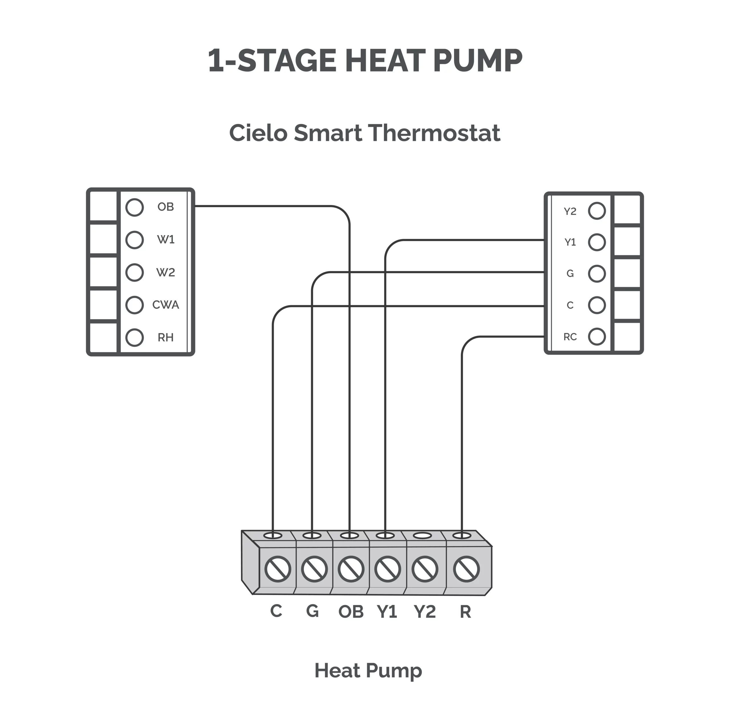
Single-Stage Heat Pump (1H/1C)
- Terminals used: Rc, C, Y1, G, O/B
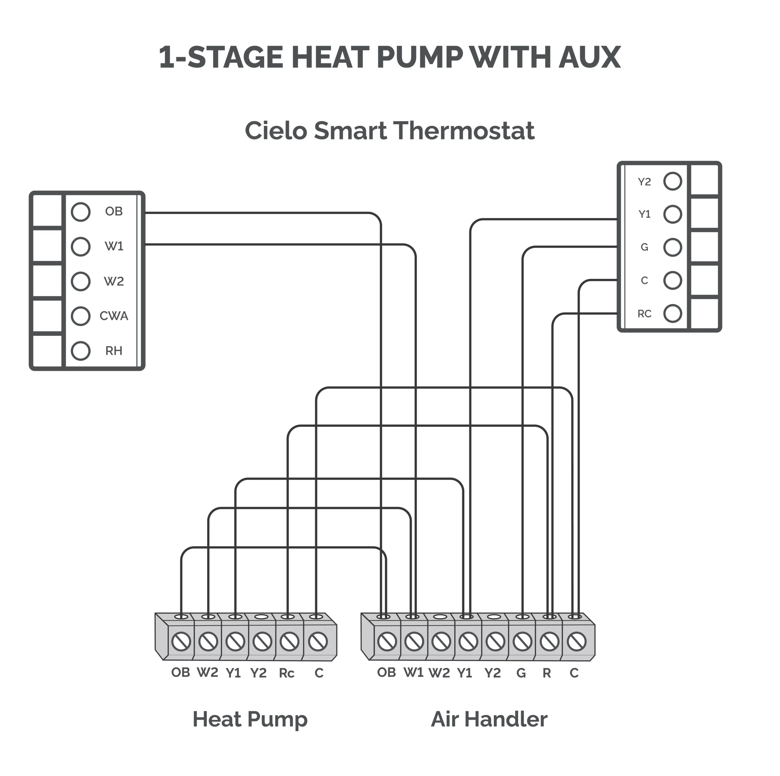
Single-Stage Heat Pump With Aux Heat (2H/1C)
- Terminals used: Rc, C, Y1, G, O/B, W1 (for AUX)
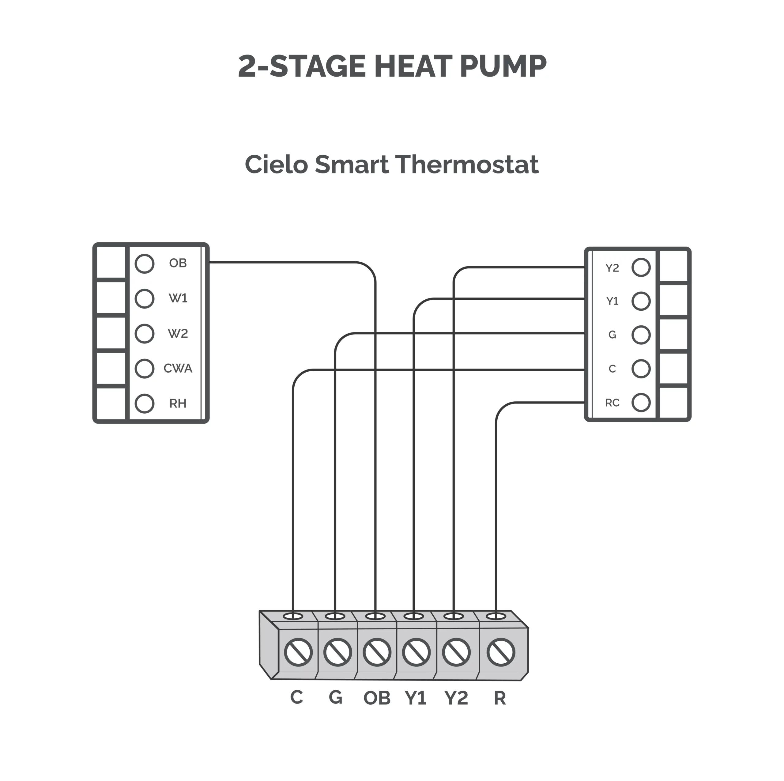
2-Stage Heat Pump (1H/2C)
- Terminals used: Rc, C, Y1, Y2, G, O/B
2-Stage Heat Pump With Aux Heat
- Terminals used: Rc, C, Y1, Y2, G, O/B, W1
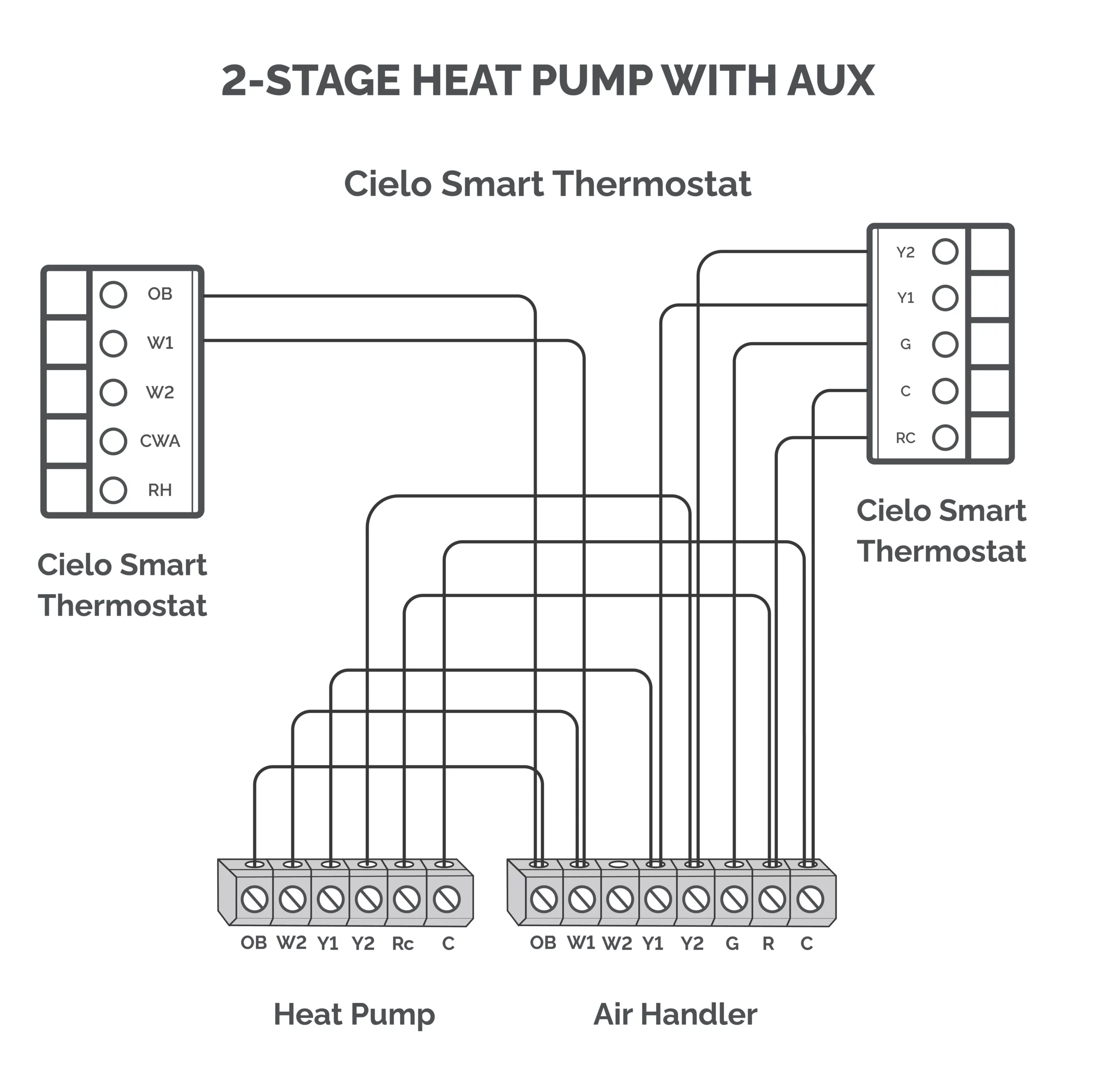
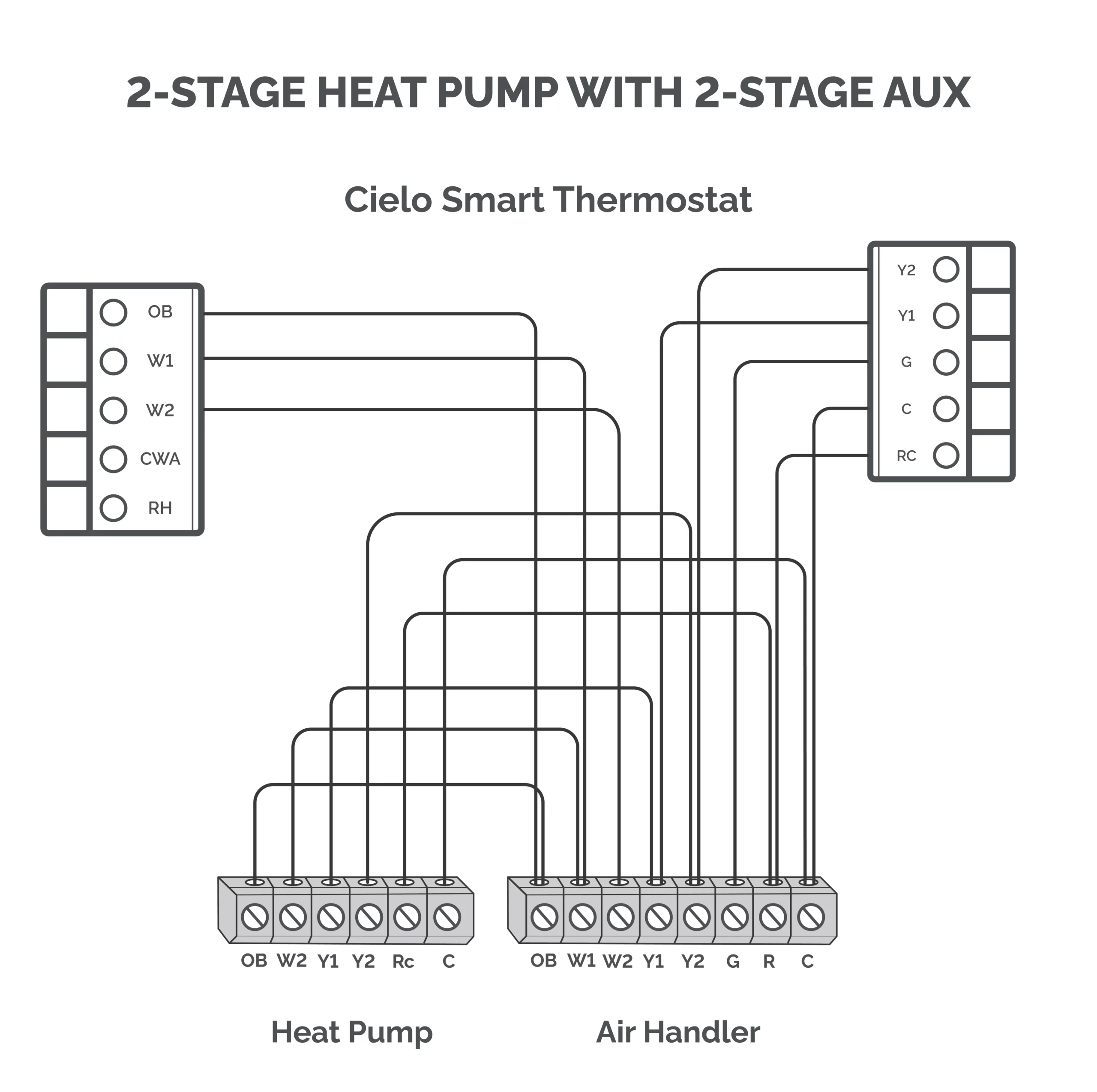
2-Stage Heat Pump With 2 Stage Aux Heat
- Terminals used: Rc, C, Y1, Y2, G, O/B, W1, W2
How to Install a Cielo Smart Thermostat With a Heat Pump
Here is a step-by-step guide to installing a Cielo Smart Thermostat with a heat pump system.
Tools & Materials Required
Before beginning the installation, ensure you have the following on hand:
- Drill with a 3/16″ drill bit
- Small flathead screwdriver
- Phillips screwdriver
- Wire stripper (optional)
- Hammer (optional)
- Pencil (optional)
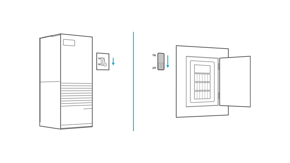
1. Turn Off the Power
Turn off the power to your heat pump by shutting off the circuit breaker or your unit’s master switch.
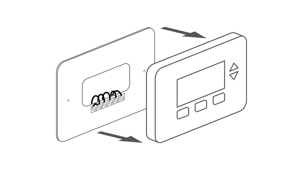
2. Verify the Wiring
- Go to your current thermostat and remove its faceplate.
- Use a non-voltage tester to ensure that no power is coming to the thermostat.
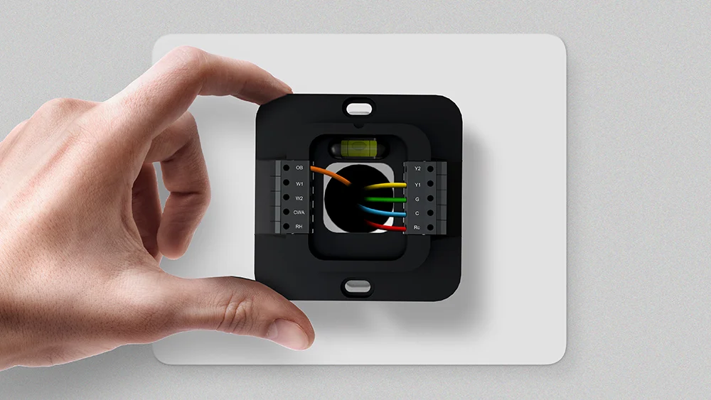
- Make sure there are at least 5 wires available for use – R/Rc, Y/Y1, G, C, O/B.
If your system does not have a C-wire, you can use the C-wire adapter included in the box. Refer to the installation guide for instructions on setting up a Cielo smart thermostat without a C-wire.
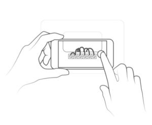
- Take a picture of the wiring setup. It will help you connect the wires later on.
4. Remove the Old Thermostat
- Disconnect the old wires and take off the old backplate.
- Label the wires with the wire labels included in the box.
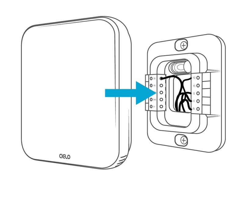
5. Install the New Thermostat
- Screw in the new backplate and take out the wires from the holes in the plate.
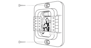
- Insert each wire into its corresponding terminal, using your reference photo taken earlier.
- Once the wiring is complete, align the Cielo Smart Thermostat with the backplate and press it gently until it clicks into place.
Final Checklist
Before powering everything back on, go through these final checks:
- Gently tug each wire to ensure it is securely connected to the terminal.
- Double-check that each wire is connected to the correct terminal.
- Gently push the excess wires back into the center hole of the backplate to ensure no drafts come through.
Troubleshooting Common Wiring Problems
Identify and resolve common thermostat wiring issues to ensure smooth heat pump operation.
-
Thermostat Heating When Set to Cool or Vice Versa
The most common issue after installing a smart thermostat is the system blowing hot air when it’s set to cool, or blowing cold air when it’s set to heat. This is either due to incorrect wiring or an incorrect system configuration.
Make sure your O or B wire is connected to the O/B terminal. Also, verify that the O/B reversing valve is energized on the correct setting. If the setting is incorrect, you’ll receive heat when calling for cooling and cooling when the system is set to heat mode.
Check out this helpful guide on what you should set your thermostat reversing valve to.
-
Thermostat Not Powering On
If the thermostat fails to power on, the issue is most commonly related to the power supply wiring. Begin by inspecting the R wire, which delivers 24V power to the thermostat. Also check the C wire, which completes the circuit and ensures a stable, continuous power supply. Loose power wires are one of the most common causes of a thermostat not turning on. Verify that both wires are firmly secured in their respective terminals and that there is no visible damage to either connection.
-
System Short Cycling
Short cycling occurs when the system turns on and off repeatedly, and sometimes it can be a wiring-related issue. Begin by inspecting all terminal connections for loose, improperly secured, or incorrectly placed wires. Even a partially unseated wire can disrupt communication between the thermostat and the system, causing erratic behavior.
In Conclusion
Heat pump thermostat wiring requires careful attention to detail, as it differs from conventional HVAC systems. By following the correct wiring practices and verifying connections at the unit, you can minimize errors and prevent system issues. A properly wired thermostat not only ensures efficient heating and cooling but also helps maintain comfort, reliability, and energy efficiency in the long run.
Frequently Asked Questions
Do I Need a C Wire for a Heat Pump Thermostat?
A C-wire is necessary if you are installing a smart thermostat to control your heat pump. The C-wire provides a continuous power source needed for Wi-Fi connectivity, touch display, and smart features.
Does My Heat Pump Use an O or B Wire?
It depends on your system’s reversing valve configuration. In most systems, the O wire is used for cooling (energizing the reversing valve in cooling mode). Some systems use a B wire for energizing the reversing valve in heat mode. To determine which one your system uses, always refer to your manufacturer’s specifications or existing wiring setup.